уторак, 14. мај 2019.

32-bit FPGA-based computer

Going 32-bit

There are follow-ups:
- implemented BLIT instruction,
- adding SPI interface to my FPGA computer,
- making BASIC interpreter for my FPGA platform,
- using GCC on my FPGA platform,
- added cache controller,
- new VGA display mode,
- booting from the SD card.


I have upgraded my FPGA-based computer from 16-bit to 32-bit. It now has 16 registers, each 32-bit. It uses 32MB SDRAM which exists on the DE0-NANO board, but it also uses static RAM for the video memory (frame buffer), for both text and graphics mode. It is approx. 40 KB of static RAM.

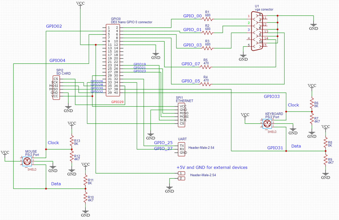
FPGA Computer Schematics

Memory management

If was quite painful to make the computer work with the SDRAM. The 32MB SDRAM needs a special controller to be used. I have found one useful controller on the github:

Since there are two types of memory in this computer (dynamic and static), I had to make a decision how to layout the memory. First 40KBs are used for the static RAM (all interrupt vectors, text and graphics video RAM and sprite definition memory). After that, the rest of the memory is in the SDRAM (up until 32MB).

If there is a need to read from the memory, this is how it is done. Let's suppose that we need to read 16 bits from the PC + 2 address:

addr <= (pc + 2) >> 1;
next_state <= EXECUTE;
state <= READ_DATA;

We need to set the next_state register to the state to which we want to return, when the read is done. Then, the CPU goes to the READ_DATA state.

READ_DATA: begin
if (addr >= SDRAM_START_ADDR) begin
waiting_sdram <= 1;
addr_o <= addr;
rd_enable_o <= 1'b1;
if (busy_i) begin
state <= READ_WAIT;
end
end
else begin
memrd <= 1'b1;
memwr <= 1'b0;
state <= READ_WAIT;
end
end

In this READ_DATA state, the CPU puts the address to the SDRAM address bus (addr_o), and sets the rd_enable to 1. Then it waits until the SDRAM is ready to read (busy_i is 1). When the SDRAM controller starts reading, the CPU goes to the READ_WAIT state. 

READ_WAIT: begin
if (addr >= SDRAM_START_ADDR) begin
rd_enable_o <= 1'b0;
if (rd_ready_i) begin
waiting_sdram <= 0;
data_r <= rd_data_i;
state <= next_state;
end
end
else begin
memrd <= 1'b0;
memwr <= 1'b0;
data_r <= data;
state <= next_state;
end
end

The READ_WAIT state finishes when the data is obtained from the memory (the actual data is in the data_r register).  It takes approx. 6 cycles (at 100 MHz) to fully obtain data from the memory (from READ_DATA to READ_WAIT, both to be finished). Then, the CPU goes to the next_state, as being set before this reading operation has been started.

Regarding writing to the SDRAM memory, let's suppose that we want to put something on the stack:

addr <= (regs[SP] - 2'd2) >> 1;
data_to_write <= regs[ir[11:8]][15:0];
// move sp to the next location
regs[SP] <= regs[SP] - 2'd2;
next_state <= EXECUTE;
state <= WRITE_DATA;

We need to set the next_state register to the state to which we want to return, when the write is done. Then, the CPU goes to the WRITE_DATA state.

WRITE_DATA: begin
if (addr >= SDRAM_START_ADDR) begin
waiting_sdram <= 1;
addr_o <= addr;
wr_data_o <= data_to_write;
wr_enable_o <= 1'b1;
if (busy_i)
state <= WRITE_WAIT;
end
else begin
memrd <= 1'b0;
memwr <= 1'b1;
state <= WRITE_WAIT;
end
end

In the WRITE_DATA state, the CPU would set the address to be written (addr_o), data to be written (wr_data_o), and would set the wr_enable_o to 1. Then it would wait for the controller to notify that it is ready to write (busy_i is 1). Then the CPU goes to the WRITE_WAIT state.

WRITE_WAIT: begin
if (addr >= SDRAM_START_ADDR) begin
wr_enable_o <= 1'b0;
if (~busy_i) begin
waiting_sdram <= 0;
state <= next_state;
end
end
else begin
memrd <= 1'b0;
memwr <= 1'b0;
state <= next_state;
end
end

The WRITE_WAIT state finishes when the data is saved to the memory.  It takes approx. 6 cycles (at 100 MHz) to fully write data to the memory (from WRITE_DATA to WRITE_WAIT, both to be finished). Then, the CPU goes to the next_state, as being set before this writing operation has been started.

CPU redesign

The CPU itself was redesigned, too. It now has quite rich instruction set, 32-bit, 16-bit and 8-bit instructions, floating point (32-bit, single precision), and three interrupts:
- IRQ0 is the timer interrupt (triggered when a given number of milliseconds have been counted),
- IRQ1 is the UART interrupt (triggered when a byte has arrived), and
- IRQ2 is the PS/2 interrupt (triggered, whenever a key is pressed on the PS/2 keyboard).

The timer IRQ was made this way: there is a counter which is incremented every millisecond. There is a timer port which initially holds zero. The programmer needs to set the number of milliseconds to be counted after which the interrupt would occur. It is done using the OUT instruction:

mov.s r0, 0x0001 ; JUMP opcode
mov.s r1, TIMER_HANDLER_ADDR ; timer vector address
st.s [r1], r0
mov.w r0, timer_triggered
mov.s r1, TIMER_HANDLER_ADDR + 2
st.w [r1], r0 ; the timer IRQ handler has been set


move.w r0, 50  ; set the timer interrupt for every 50 milliseconds
out 129, r0

The assembler code above would set the internal timer register to the given value (50). Every millisecond the CPU would increase another internal register, named timer_counter, and when the timer_counter reaches the timer, that would trigger the timer interrupt:

if (timer && (timer_counter < timer)) begin
timer_counter <= timer_counter + 1'b1;
end
else if (timer && (timer_counter == timer)) begin
irq[0] <= 1;
timer_counter <= 0;
end 

At the end of each instruction execution, there is a check for the interrupts:

if (irq_r[0]) begin
// timer
pc <= 16'd8;
addr <= 16'd4;
irq_r[0] <= 0;
end 

If there is a timer interrupt, the CPU would jump to the TIMER_HANDLER_ADDR, which is 8.

FPGA Raspbootin loader

I have modified the FPGA Raspbootin loader so it would now load the FPGA itself, instead of relying on the Quartus II studio for that. This means that I can now control the Computer from a single application - FPGA Raspbootin:


The loader now first loads the design into the FPGA (unless it is flashed - then no loading the design file is needed), and then it loads the selected binary into the computer. Here is the Java code for loading the design into the FPGA (by starting the quartus_pgm.exe program):

public static void runFpga() {
Process process;
try {
process = new ProcessBuilder(qpfPath,
"-c", "usb-blaster",
"-m", "jtag",
"-o", "P;" + sofPath).start();
InputStream is = process.getInputStream();
InputStreamReader isr = new InputStreamReader(is);
BufferedReader br = new BufferedReader(isr);
String line;
while ((line = br.readLine()) != null) {
  System.out.println(line);
}
} catch (IOException e) {
e.printStackTrace();
}
}

The qpfPath points to the quartus_pgm.exe file, which acutally loads the design into the FPGA. Usually it is something like: C:\altera\13.0\quartus\bin\quartus_pgm.exe

The design file has the *.sof extension, and it is loaded into the FPGA using the quartus_pgm.exe program. The *.sof file is built during the compilation of the design inside the Quartus II studio. In my program, the path to the *.sof file is in the sofPath variable.

More details about loading FPGA design on the DE0-NANO FPGA board can be found here:
https://mvidakovic.blogspot.com/2019/10/flashing-de0-nano-fpga-board.html

Conclusion

The 32-bit rework took more time than I expected, mainly because I wanted to use the built-in 32MB SDRAM. Then I added the floating-point instructions and now it looks quite stable. I have used about 80% of the FPGA, so I could try to do something more later.

The CPU is on the github:
https://github.com/milanvidakovic/FPGAComputer32

The assembler examples are on the github:
https://github.com/milanvidakovic/Assembler32

The Raspbootin64 boot loader is on the github:
https://github.com/milanvidakovic/FPGARaspbootin64Client

The Emulator is on the github:
https://github.com/milanvidakovic/FPGAEmulator32


Hardware watchdog for Raspberry Pi Zero

This is an additional attempt  to make Raspberry Pi more reliable (the fist was to make RPI file system read-only). I have noticed that RPI sometimes does not boot after it was properly powered down. Sometimes it can freeze during the normal operation. The solution for those situations is a watchdog timer. The idea is that the watchdog would reset the device unless the device pings it on a regular basis.

RPI does have a built-in watchdog, but as far as I could understand, it is a part of the OS. But what if the OS did not boot? You would end up with a frozen machine.

That is the reason why I tried to find some hardware-based watchdog implementations for the RPI. To be more precise, I wanted to manage RPI Zero, since Zeros are used to gather sensor data all around my flat.

There are several hardware implementations based on the 555 timer IC. It is a very versatile IC and one setup that I have found useful for the watchdog implementation is shown in the picture below:


The RES wire goes to the reset pin on the RPI Zero (marked as RUN on the board):


The RUN pin on the Zero needs to be connected to the ground in order to reset the device.

The watchdog is pinged via GPIO pin (in this particular example, it is GPIO pin 21). To do so, it is sufficient to periodically ping the watchdog via GPIO pin 21. Here is the Python code which pings the watchdog:

import RPi.GPIO as GPIO
import time
import threading
import os
import sys
# Port which shorts the capacitor in the watchdog(GPIO 21)
# pin 40
PORT_OFF = 21
# GPIO pin enumeration
GPIO.setmode(GPIO.BCM)
GPIO.setup(PORT_OFF, GPIO.OUT)
#short the capacitor
GPIO.output(PORT_OFF, 0)
time.sleep(0.250)
# disconnect
GPIO.cleanup()

RPI pings the watchdog by shorting the 100uF capacitor to the ground. It is done by setting the logical 0 to the GPIO 21. The capacitor is shorted to ground via 200 Ohm resistor, and that just restarts the 555. If the capacitor is not shorted in time, the 555 would send the logical 0 to the RUN pin on the RPI and that would reset the device.

The period for the reset is approx. 2 minutes, and that was set using the 470K resistor and 100uF capacitor. Increase one of them, and you will get the longer period.

I have set the Python script to ping the watchdog at the boot time, and then to be called each minute. The first ping occurs just 15 seconds after the boot.

It is important to set the RPI file system to read-only. If not done so, the reset would probably corrupt the SD card data. I have found a good script for setting up the RPI file system to read-only


понедељак, 14. јануар 2019.

Java Swing GUI Application Full Screen on Linux

How to make your Java Swing application full screen on Linux

I have found this code on the stack overflow site:

static public boolean fullScreen(final JFrame frame, boolean doPack) {

  GraphicsDevice device = frame.getGraphicsConfiguration().getDevice();
  boolean result = device.isFullScreenSupported();

  if (result) {
    frame.setUndecorated(true);
    frame.setResizable(true);

    frame.addFocusListener(new FocusListener() {
      @Override
        public void focusGained(FocusEvent arg0) {
          frame.setAlwaysOnTop(true);
}

        @Override
        public void focusLost(FocusEvent arg0) {
          frame.setAlwaysOnTop(false);
        }
    });

    if (doPack)
      frame.pack();
      device.setFullScreenWindow(frame);
    } else {
      frame.setPreferredSize(
        frame.getGraphicsConfiguration().getBounds().getSize());


      if (doPack)
        frame.pack();

      frame.setResizable(true);

      frame.setExtendedState(Frame.MAXIMIZED_BOTH);
      boolean successful = frame.getExtendedState() == Frame.MAXIMIZED_BOTH;

      frame.setVisible(true);

      if (!successful)
          frame.setExtendedState(Frame.MAXIMIZED_BOTH);
    }
    return result;
}

This is important peace of code if you want to make a full screen application that works the same on both Linux and Windows OS.

For example, if you just write this:

setExtendedState(JFrame.MAXIMIZED_BOTH);
setUndecorated(true);

... the code above would make a full screen on Windows, but on Linux you would still see the task bar:


The code that I found on the stack overflow makes a full screen on both Windows and Linux:


At the top of the screen, you can see burnt in pixels from the previous version of software which did not do the full screen (it had the task bar on it).


Read only File System on Raspberry Pi

How to make the file system of the Raspberry Pi read only

There is an update to this story: https://mvidakovic.blogspot.com/2019/08/the-ultimate-read-only-file-system-on.html

I have found this repo on the gitlab and decided to fork it:
https://github.com/milanvidakovic/rpi-readonly

Why is this important? Well, Raspberry Pi usually uses micro SD card as a drive. I have been using Raspberry Pi and similar computers since 2014 and have seen SD card crashes too many times. Last time, my RPI2 crashed on regular poweroff (sudo poweroff). The SD card in it was new, so it was not the old faulty card. Simply, RPI tends to crash SD cards. Sooner or later, it will crash it.

There are numerous tutorials on how to make Raspbian file system read only. However, this repo above is the only one that made me able to make a desktop version of Raspbian read only. What I mean is that most of the tutorials help you make your headless server-only Raspbian become read only. However, if you have a Raspbian with the GUI, then this script is the only one that I was able to make work (not saying it is the only one in the world).

субота, 24. новембар 2018.

Hardware sprites on the FPGA computer

Adding hardware sprites

This is a follow-up of the FPGA computer post. 

I have added hardware sprites to the graphic mode of my FPGA computer. It now supports up to 16 sprites, each one being 16x16pixels in size. Here is how it looks on the monitor:
In emulator, it looks the same:


Each sprite is defined by the 8-byte structure:
  • sprite definition data address (2 bytes)
  • x coordinate (2 bytes)
  • y coordinate (2 bytes)
  • transparent color (2 bytes).
The sprite structure for the first sprite starts at address of 56 decimal. Each next sprite structure starts 8 bytes later. 

Sprite definition data consists of 16 lines, each line described by 16 pixels, each pixel defined by 4 bits: xrgbThis means that one sprite line consists of 8 bytes (two pixels per byte), so total bytes needed for the sprite definition is 8x16 bytes == 128 bytes.

Here is the example of showing one sprite at (25, 25) in assembler language:

  mov r0, sprite_def
  mov r1, 56
  st [r1], r0  ; sprite definition is at sprite_def address
  mov r0, 25
  st [r1 + 2], r0  ; x = 25  at addr 58
  mov r0, 25
  st [r1 + 4], r0  ; y = 25  at addr 60
  mov r0, 0
  st [r1 + 6], r0  ; transparent color is black (0) at addr 62
  ; sprite definition
sprite_def:
  #d16 0x0000, 0x0000, 0x0000, 0x0000  ; 0
  #d16 0x0000, 0x000f, 0xf000, 0x0000  ; 1
  #d16 0x0000, 0x000f, 0xf000, 0x0000  ; 2
  #d16 0x0000, 0x000f, 0xf000, 0x0000  ; 3
  #d16 0x0000, 0x004f, 0xf400, 0x0000  ; 4
  #d16 0x0000, 0x004f, 0xf400, 0x0000  ; 5
  #d16 0x0000, 0x044f, 0xf440, 0x0000  ; 6
  #d16 0x0000, 0x444f, 0xf444, 0x0000  ; 7
  #d16 0x0004, 0x444f, 0xf444, 0x4000  ; 8
  #d16 0x0044, 0x444f, 0xf444, 0x4400  ; 9
  #d16 0x0400, 0x004f, 0xf400, 0x0040  ; 10
  #d16 0x0000, 0x004f, 0xf400, 0x0000  ; 11
  #d16 0x0000, 0x004f, 0xf400, 0x0000  ; 12
  #d16 0x0000, 0x041f, 0xf140, 0x0000  ; 13
  #d16 0x0000, 0x4111, 0x1114, 0x0000  ; 14
  #d16 0x0004, 0x4444, 0x4444, 0x4000  ; 15

How this stuff works? First of all, I had to decide how to implement sprites. I have decided to fetch all sprite data during the vertical blanking interval (VBI). During VBI, the video subsystem starts fetching sprite data by reading the 8-byte sprite structure starting from the address of 56 decimal (the address and data bus are 16-bit, so the computer is word-oriented (reads two bytes at the same time), and the actual address is set to
56 >> 1 == 28):

if ((x >= 640) && (y == 479) && (state == IN_LINE)) begin
  // when we start the vertical blanking, 
  // we need to fetch in advance the first sprite data
  state <= READ_SPRITES;
  sprite_counter <= 4'b0;
  rd <= 1'b1;
  wr <= 1'b0;
  mem_read <= 1'b1;
  addr <= 16'd28;    // prepare to read sprite definition address
end

In the next clock cycle, the system is in the READ_SPRITES state. The first thing that we do in the READ_SPRITES state is fetching the sprite definition address which is present at the data bus, since we have initiated a memory read from within the previous state.

Then we need to prepare the address bus for the next state in which we will fetch the x coordinate of the sprite. We do that by setting the address bus to (58 + (sprite_counter << 3)) for all sprites, having the sprite_counter iterating from 0 to 15:

READ_SPRITES: begin
  sprite_addr[sprite_counter] <= data;
  state <= READ_SPRITE_X;
  rd <= 1'b1;
  wr <= 1'b0;
  mem_read <= 1'b1;
  // prepare to read x coordinate of the sprite
  addr <= (16'd58 + (sprite_counter << 3)) >> 1;    
end

In the READ_SPRITE_X state, we fetch the x coordinate of the sprite which was ready at the data bus, and then we prepare to read the y coordinate in the next state:

READ_SPRITE_Y: begin
  sprite_y[sprite_counter] <= data;
  state <= READ_SPRITE_TRANSPARENT_COLOR;
  rd <= 1'b1;
  wr <= 1'b0;
  mem_read <= 1'b1;
  // prepare to read transparent color of the sprite  
  addr <= (16'd62 + (sprite_counter << 3)) >> 1;    
end

In the READ_SPRITE_Y state, we fetch the y coordinate of the sprite which was ready at the data bus, and then we prepare to read the sprite transparent color in the next state:

READ_SPRITE_TRANSPARENT_COLOR: begin
  sprite_transparent_color[sprite_counter] <= data[3:0];
  state <= READ_SPRITE_DATA;
  rd <= 1'b1;
  wr <= 1'b0;
  mem_read <= 1'b1;
  line_counter <= 16'b0;
  word_counter <= 4'b0;
  // read sprite definition bytes
  addr <= sprite_addr[sprite_counter] >> 1;    
end

In the READ_SPRITE_TRANSPARENT_COLOR state, we fetch the transparent color of the sprite, and then put the address of the sprite definition to the address bus so we can fetch it in the next state:

READ_SPRITE_DATA: begin
  if (line_counter < 16) begin
    case (word_counter) 
    0:  sprite_pixels[sprite_counter][line_counter][63:48] <= data;
    1:  sprite_pixels[sprite_counter][line_counter][47:32] <= data;
    2:  sprite_pixels[sprite_counter][line_counter][31:16] <= data;
    3:  sprite_pixels[sprite_counter][line_counter][15:0]  <= data;
    endcase
    state <= READ_SPRITE_DATA;
    rd <= 1'b1;
    wr <= 1'b0;
    mem_read <= 1'b1;
    if (word_counter < 3) begin
      word_counter = word_counter + 1'b1;
    end
    else begin
      word_counter = 1'b0;
      line_counter = line_counter + 16'b1;
    end
    // read sprite definition bytes
    addr = (sprite_addr[sprite_counter] + ((word_counter +
           (line_counter << 2)) << 1) ) >> 1;    
  end
  else 
  begin
    if (sprite_counter < SPRITE_NUM) begin
      sprite_counter = sprite_counter + 1'b1;
      state <= READ_SPRITES;
      rd <= 1'b1;
      wr <= 1'b0;
      mem_read <= 1'b1;
      // read next sprite definition address
      addr <= (16'd56 + (sprite_counter << 3)) >> 1;   
    end
    else begin
      sprite_counter <= 4'b0;
      rd <= 1'b1;
      wr <= 1'b0;
      mem_read <= 1'b1;
      addr <= VIDEO_MEM_ADDR + 0;
      state <= V_BLANK;
    end
  end
end

In the READ_SPRITE_DATA state we start reading sprite definition from the memory. We do it for each line of the sprite (16 lines per sprite), and within the line, for each word containing four pixels of the sprite line definition.

When we finish loading all sprite definition data for the current sprite, then we do the same for other sprite until we read all sprite definition data. Then we then set the address bus to load the pixel data at the (0, 0) position on the screen, and move to the V_BLANK state:

V_BLANK: begin
  pixels <= data;
  state <= SCAN_IDLE;
  rd <= 1'bz;
  wr <= 1'bz;
  mem_read <= 1'b0;
end

In the V_BLANK state we read the pixels of the frame buffer at the (0, 0) coordinate, and then set the all the control signals to high impedance and set the state to SCAN_IDLE. We will leave the SCAN_IDLE state when the the time comes to start displaying pixels starting from the (0, 0) coordinate.

Displaying sprite data

During the scanline processing, we need to display both original pixels from the frame buffer as well as the sprite data, and we need to make sure that the original pixels must be displayed through the transparent sprite color.

This is done in the following code:

if (valid) begin
  for (i = 0; i < SPRITE_NUM; i = i+1) begin
    if ((sprite_addr[i] != 16'b0) &&
       (xx >= sprite_x[i]) &&
       (xx < (sprite_x[i] + 16)) &&
       (yy >= sprite_y[i]) &&
       (yy < (sprite_y[i] + 16))) begin

      sprite_found = 1'b1;
      if (
        sprite_pixels[i][yy - sprite_y[i]][60-(((xx - sprite_x[i]) << 2) ) + 0] != sprite_transparent_color[i][0] ||
        sprite_pixels[i][yy - sprite_y[i]][60-(((xx - sprite_x[i]) << 2) ) + 1] != sprite_transparent_color[i][1] ||
        sprite_pixels[i][yy - sprite_y[i]][60-(((xx - sprite_x[i]) << 2) ) + 2] != sprite_transparent_color[i][2]
      ) begin
        r <= sprite_pixels[i][yy - sprite_y[i]][60-(((xx - sprite_x[i]) << 2) ) + 0] == 1'b1;
        g <= sprite_pixels[i][yy - sprite_y[i]][60-(((xx - sprite_x[i]) << 2) ) + 1] == 1'b1;
        b <= sprite_pixels[i][yy - sprite_y[i]][60-(((xx - sprite_x[i]) << 2) ) + 2] == 1'b1;
      end 
      else begin
        r <= pixels[12 - ((xx & 3) << 2) + 0] == 1'b1;
        g <= pixels[12 - ((xx & 3) << 2) + 1] == 1'b1;
        b <= pixels[12 - ((xx & 3) << 2) + 2] == 1'b1;
      end
    end 
  end
  if (!sprite_found) begin
    r <= pixels[12 - ((xx & 3) << 2) + 0] == 1'b1;
    g <= pixels[12 - ((xx & 3) << 2) + 1] == 1'b1;
    b <= pixels[12 - ((xx & 3) << 2) + 2] == 1'b1;
  end
  else begin
    sprite_found = 1'b0;
  end
end
else begin
  // blanking -> no pixels
  r <= 1'b0;
  g <= 1'b0;
  b <= 1'b0;
end
end

The most interesting thing is the "for loop". It is not a loop - it actually repeats the Verilog code SPRITE_NUM times. That is the most important thing to understand about "loops". You don't have the linear code to be executed multiple times. Instead, everything is a giant state machine that pulses with the clock signals and the "for loop" just unwraps the code multiple times, and all that unwrapped code "works" at the same time.

So, when we have this Verilog code:
 for (i = 0; i < SPRITE_NUM; i = i+1) begin
    if ((sprite_addr[i] != 16'b0) &&
       (xx >= sprite_x[i]) &&
       (xx < (sprite_x[i] + 16)) &&
       (yy >= sprite_y[i]) &&
       (yy < (sprite_y[i] + 16))) begin

It actually does this:
    if ((sprite_addr[0] != 16'b0) &&
       (xx >= sprite_x[0]) &&
       (xx < (sprite_x[0] + 16)) &&
       (yy >= sprite_y[0]) &&
       (yy < (sprite_y[0] + 16))) begin

...
    end
    if ((sprite_addr[1] != 16'b0) &&
       (xx >= sprite_x[1]) && 
       (xx < (sprite_x[1] + 16)) && 
       (yy >= sprite_y[1]) && 
       (yy < (sprite_y[1] + 16))) begin
...
    end
...


The code with the "for loop" does the same thing for all sprites:
  1. if the spite definition address is not zero, and current x and y coordinates of the scanline are within sprite coordinates, then we put the current sprite pixel color to the output r, g and b signals, or we put the original frame buffer pixel colors, if the current sprite pixel is transparent one (the color of the current sprite pixel is the transparent color).
  2. else, if the current x and y coordinates of the scanline are outside of the sprite coordinates, we put the frame buffer pixel data to the r, g and b output signals.
  3. else, it must be blanking interval, so put zeros to r, g and b to output signals.

Conclusion

This implementation of sprites requires that the vga module has its own internal memory which is filled with the sprite data from the main memory. Then, during the scanline processing, sprite pixels are combined with frame buffer pixels in a way that sprite pixels are placed "over" the frame buffer pixels, unless the current sprite pixel is the transparent one. If that is the case, then the frame buffer pixel is "shown" through the sprite.

The great thing about hardware sprites is that they do not consume processor time at all. Everything is done in hardware and showing sprites actually requires just to have the sprite definition address set to non-zero value.

уторак, 6. новембар 2018.

MozillaThunderbird still working when you close the program

How to fix the problem when Mozilla Thunderbird remains in memory after closing

I use Thunderbird for more than ten years. I simply cannot migrate to anything else. Unfortunately, Thunderbird has one annoying feature (or a bug): it stays in memory when you close the program using the X button at the top right corner. Why is that bad? Well, if you try to close the Thunderbird that way, and then you start it again, it will start behaving oddly. It will either stop recieving mails, or get stuck when sending an email. It will simply work bad.

To remedy this, it is recommended that you close the Thunderbird by using the Exit option from the File menu. However, I got used to close the application by clicking on the X button so much, that it is annoying for me to change my habits and do some extra clicks (instead of a single one).

Even worse, some people claim that the Thunderbird remains active even if you go to the File menu and choose the Exit option. I am almost sure that it happend with my Thunderbird too, couple of times.

So, I have decided to do something with that problem, and today I have created a batch file with the following content:

taskkill /IM thunderbird.exe /F
start "Thunderbird" "c:\Program Files (x86)\Mozilla Thunderbird\thunderbird.exe"

Instead of clicking on the Thunderbird icon, I click on the shortcut on my desktop which points to this batch file. 

What this batch file does? It kills the remaining Thunderbird instance before starting a new one. The "/F" switch forces the kill (just like the "kill -9" in Linux), while "/IM thunderbird.exe" is the image name of the process to be killed.

Make desktop shortcut to a batch file work on Windows 10

This brings us to the second problem: on Windows 10, if you create a shortcut on the Desktop which points to a batch file, it doesn't work (if you double click on that shortcut, nothing happens).

You need to edit the newly created shortcut and add the following text in the Target field, just before the original command:

C:\Windows\System32\cmd.exe /c "original command"

For example, my batch file is in the C:\Tools folder. This means that the original shortcut had the content of the Target field like this:

C:\Tools\thunderbird.bat

Now, the modified Target looks like this:

C:\Windows\System32\cmd.exe /c "C:\Tools\thunderbird.bat"


Pay attention that you need to put the original command in double quotes.


недеља, 14. октобар 2018.

Electronic art or Raspberry PI as a wall clock

Raspberry pi as a wall clock

In one of my posts, I have described how I have used old Android phones to show time and temperature. Both phones were connected to the power supply, and without a battery. (One of the highlights of that post was the manual how to remove the battery and yet have the phone working). In that post I was more worried about the display being turned on constantly, 365x24, than anything else. I thought that since I have removed the battery, the only thing that could break would be the screen, since it worked constantly, day and night.

Well, I was wrong. Both phones died (both managed to work that way for more than a year), but it was not the display, nor the motherboard or the CPU. The WiFi module in both phones died. One interesting fact is that one of those phones (Samsung Galaxy S plus) had the Super AMOLED capacitive touchscreen, and that screen did have a kind of burned pixels from my program. Not too noticeable, but existent.

When the first phone died, I had one spare RPI and one small touch screen for that RPI. I have written a small Swing Java program that connects to my weather server, pulls the data and displays that, just as the Android application on those dead phones. The program writes the information one pixel to the left every second, to save the pixels (not all pixels - those displaying the taskbar will be more burned). 

The result was - from this:
to this:


If you look carefully, you will notice that the display (and the RPI) is turned upside-down. That is because of the USB power cable, which tends to crack if it stands upright without any support (this RPI stands upright on its own). So, I have made one additional transformation of the picture to flip it. 

The small red rectangle at the lower right corner turns on and off each second to give me a visual indicator that the computer did not freeze (RPIs tend to freeze for too much reasons).

Then the second phone died. Again, I had another unused RPI and a 7-inch display purchased to be a portable HDMI monitor when I need to service my other RPIs permanently placed around the apartment. Well, that screen (and the RPI) has found its new purpose - to be a wall clock.

The only problem was that there were too many cables. I had 5V adapter which powers both RPI and the screen, the RPI and the screen. Two USB power cables and one HDMI cable.

So, instead of this phone:

I have created a kind of electronic art:


On the picture above, you can spot the power adapter at the lower left corner, RPI at the lower right corner, and the screen placed inside a portable LCD TV which died long time ago, but had the same-sized LCD display, so I was able to recycle the case.

Now, if you look closely at the picture, you will notice that the picture is not flipped. On this RPI, I don't have the problem with the power cable (everything was secured inside the frame), so I did not have to flip the picture. So I have introduced one additional configuration parameter: to flip the picture or not. 

The RPI connects to the weather server using WiFi. I plan to bring the Ethernet cable there as a next step.