Приказивање постова са ознаком pi. Прикажи све постове

субота, 17. август 2019.

The ultimate read-only file system on the SD card

This is a kind of follow-up of my previous post:
https://mvidakovic.blogspot.com/2019/01/read-only-file-system-on-raspberry-pi.html

I have recently stumbled upon this tool:
https://github.com/BertoldVdb/sdtool

I immediately forked it:
https://github.com/milanvidakovic/sdtool

The main idea behind this tool is to set one of the following command bits of the CSD register (very low level communication) of the SD card (via SPI interface):

  • TMP_WRITE_PROTECT - temporarily enable/disable write protection for the SD card,
  • PERM_WRITE_PROTECT - permanently enable write protection for the SD card (cannot be reversed).
The behavior of the temporary write protection is quite interesting: when you enable it, it will silently fail when writing to the SD card. In reality, it means that when you try to write to a file (or create a new file), you will not get any error, and you might even be able to read that file (probably because it was placed in the cache of the file system), but as soon as you reboot, you will see that there have not been any changes.

How can this be used? First of all, you should set up your Raspberry Pi file system to read-only (for example, you can use this), so it would be normal not to have writes to the SD card. Then you can use the sdtool to enable the write protection. With those two steps, you should get the ultimate protection of your SD card.

Why is this important? I have couple of RPIs which work constantly for years. My experience with SD cards and RPIs is that they eventually corrupt the SD card. Sooner or later it will happen. If you just enable the read-only file system, it seems that the SD card still gets corrupted. I don't know why, but it happened to me several times. I have changed several SD cards (different vendors, different models), and several power adapters, and still got SD cards corrupted at some point. I thought that having the file system set to read-only would not corrupt the SD card during power loss (unattended shutdown), but, unfortunately, the SD card would get corrupted anyway. 

Even if the RPi is on the UPS (doesn't get turned off improperly), it would still corrupt the SD card sooner or later. It happened too many times with my RPIs (and the Odroid, too). 

One way to fix this is to boot the device from the USB hard disk instead of SD card, but then the same problem can occur with the hard disk (although, not that bad as it occurs with the SD card). As a matter of fact, it happened once with my Odroid and once with my RPi 3 (to have the USB hard disk corrupted). In addition, why would you put the USB hard disk on your RPI 0? It is supposed to be a lightweight system, not having a hard disk that consumes more power than RPI 0.

I have found an information on some forums that a special (quite expensive) SD card types do not get corrupted at all: aMLC and SLC type. Both are significantly more expensive than the usual cards, but people claim that they simply do not get corrupted.

One funny thing - my RPI 1 has corrupted the SD card only once in almost five years, while RPI Zero and RPI 2 and 3 can corrupt the SD card in a matter of months (or even sooner). Does it have to do with the speed of the system? Is the SD card overwhelmed with data and then it goes corrupt? Why is it corrupted in the read-only mode, then? I don't know answers to all those questions. What I do know, however, is the fact that the SD card would eventually get corrupted and that is the main reason for this post.

I am now testing this temporary write protection in conjunction with the read-only file system on my RPIs, and I will update this post with my experience.

At the end, just to repeat the fact that the contacts on the SD card are actually the SPI interface contacts, meaning that all the communication with the SD card goes over the SPI interface:


среда, 3. јул 2019.

Two-way AC control

How to control the AC two way using Raspberry Pi

In my previous posts, I have described my small Home Automation system. It consists of various sensors, connected to several Raspberry Pi computers. The control was initially one-way, meaning that I could only watch sensor data on the Home Automation web site. Then I have added AC remote control support to the system. I have used the lirc library which enables user to record IR commands and then to reproduce them. The initial setup enabled users to remotely control the AC from the Home web site. However, there was no way of knowing the actual AC status (if the AC already works or not). This means that the Home web site could not display the current AC status and instead of turning the AC on, we could turn it off. That is the topic of this post - how to add the support to the Home Automation system, which can read AC status.

By default, the AC is controlled using the IR remote. I have rather old AC, which is not connected to the WiFi, so there is only one way of knowing if the AC is working or not - the status LED at the AC device. I have figured out a way to read the LED status and to feed that information to the RPI. The Idea is quite simple: glue the photo sensitive resistor to the AC status LED, and connect that resistor to the simple circuit which gives an information to the RPI if the AC is working.

This is the photo sensitive resistor - photoresistor:


Here is the circuit:

The photo resistor decreases the resistance when exposed to the light. If there is no light, the resistance is couple of hundred kilo Ohms. When lit by the AC LED, the resistance drops to the approx. 20 kilo Ohms. Since the circuit is actually a voltage divider, when LED is not lit, the voltage at the GPIO port is high, meaning logical 1. If the LED is turned on, the resistance drops, the voltage at the divider drops, and the GPIO port reads 0.

The Python code which reacts to the change of LED operation is here:

PORT_AC = 21
GPIO.setmode(GPIO.BCM)
GPIO.setup(PORT_AC, GPIO.IN)

acStatus = not GPIO.input(PORT_AC)
print 'AC STATUS: ', acStatus

def ac_edge_detected(channel):
  time.sleep(0.25) // give some time to properly read GPIO port
  print 'AC EDGE detected, channel is ', channel
  global acStatus
  acStatus = not GPIO.input(PORT_AC)
  print 'AC STATUS: ', acStatus
  requests.get('http://' + STATUS_HOST + ':8080/setAc/' + str(acStatus))

GPIO.add_event_detect(PORT_AC, GPIO.BOTH, callback=ac_edge_detected, bouncetime=50)

Here is how it looks implemented:

And here is the AC part of the Home Web application:

Conclusion

Initial AC solution provided me with the option of turning on/off AC remotely. However, the system could not know the initial and current AC status, making turning on/off unreliable. This contraption is capable of determining the AC status by observing the AC LED status. It does so by having the voltage over the photo resistor dropping when the LED is turned on.

уторак, 14. мај 2019.

Hardware watchdog for Raspberry Pi Zero

This is an additional attempt  to make Raspberry Pi more reliable (the fist was to make RPI file system read-only). I have noticed that RPI sometimes does not boot after it was properly powered down. Sometimes it can freeze during the normal operation. The solution for those situations is a watchdog timer. The idea is that the watchdog would reset the device unless the device pings it on a regular basis.

RPI does have a built-in watchdog, but as far as I could understand, it is a part of the OS. But what if the OS did not boot? You would end up with a frozen machine.

That is the reason why I tried to find some hardware-based watchdog implementations for the RPI. To be more precise, I wanted to manage RPI Zero, since Zeros are used to gather sensor data all around my flat.

There are several hardware implementations based on the 555 timer IC. It is a very versatile IC and one setup that I have found useful for the watchdog implementation is shown in the picture below:


The RES wire goes to the reset pin on the RPI Zero (marked as RUN on the board):


The RUN pin on the Zero needs to be connected to the ground in order to reset the device.

The watchdog is pinged via GPIO pin (in this particular example, it is GPIO pin 21). To do so, it is sufficient to periodically ping the watchdog via GPIO pin 21. Here is the Python code which pings the watchdog:

import RPi.GPIO as GPIO
import time
import threading
import os
import sys
# Port which shorts the capacitor in the watchdog(GPIO 21)
# pin 40
PORT_OFF = 21
# GPIO pin enumeration
GPIO.setmode(GPIO.BCM)
GPIO.setup(PORT_OFF, GPIO.OUT)
#short the capacitor
GPIO.output(PORT_OFF, 0)
time.sleep(0.250)
# disconnect
GPIO.cleanup()

RPI pings the watchdog by shorting the 100uF capacitor to the ground. It is done by setting the logical 0 to the GPIO 21. The capacitor is shorted to ground via 200 Ohm resistor, and that just restarts the 555. If the capacitor is not shorted in time, the 555 would send the logical 0 to the RUN pin on the RPI and that would reset the device.

The period for the reset is approx. 2 minutes, and that was set using the 470K resistor and 100uF capacitor. Increase one of them, and you will get the longer period.

I have set the Python script to ping the watchdog at the boot time, and then to be called each minute. The first ping occurs just 15 seconds after the boot.

It is important to set the RPI file system to read-only. If not done so, the reset would probably corrupt the SD card data. I have found a good script for setting up the RPI file system to read-only


понедељак, 14. јануар 2019.

Read only File System on Raspberry Pi

How to make the file system of the Raspberry Pi read only

There is an update to this story: https://mvidakovic.blogspot.com/2019/08/the-ultimate-read-only-file-system-on.html

I have found this repo on the gitlab and decided to fork it:
https://github.com/milanvidakovic/rpi-readonly

Why is this important? Well, Raspberry Pi usually uses micro SD card as a drive. I have been using Raspberry Pi and similar computers since 2014 and have seen SD card crashes too many times. Last time, my RPI2 crashed on regular poweroff (sudo poweroff). The SD card in it was new, so it was not the old faulty card. Simply, RPI tends to crash SD cards. Sooner or later, it will crash it.

There are numerous tutorials on how to make Raspbian file system read only. However, this repo above is the only one that made me able to make a desktop version of Raspbian read only. What I mean is that most of the tutorials help you make your headless server-only Raspbian become read only. However, if you have a Raspbian with the GUI, then this script is the only one that I was able to make work (not saying it is the only one in the world).

недеља, 14. октобар 2018.

Electronic art or Raspberry PI as a wall clock

Raspberry pi as a wall clock

In one of my posts, I have described how I have used old Android phones to show time and temperature. Both phones were connected to the power supply, and without a battery. (One of the highlights of that post was the manual how to remove the battery and yet have the phone working). In that post I was more worried about the display being turned on constantly, 365x24, than anything else. I thought that since I have removed the battery, the only thing that could break would be the screen, since it worked constantly, day and night.

Well, I was wrong. Both phones died (both managed to work that way for more than a year), but it was not the display, nor the motherboard or the CPU. The WiFi module in both phones died. One interesting fact is that one of those phones (Samsung Galaxy S plus) had the Super AMOLED capacitive touchscreen, and that screen did have a kind of burned pixels from my program. Not too noticeable, but existent.

When the first phone died, I had one spare RPI and one small touch screen for that RPI. I have written a small Swing Java program that connects to my weather server, pulls the data and displays that, just as the Android application on those dead phones. The program writes the information one pixel to the left every second, to save the pixels (not all pixels - those displaying the taskbar will be more burned). 

The result was - from this:
to this:


If you look carefully, you will notice that the display (and the RPI) is turned upside-down. That is because of the USB power cable, which tends to crack if it stands upright without any support (this RPI stands upright on its own). So, I have made one additional transformation of the picture to flip it. 

The small red rectangle at the lower right corner turns on and off each second to give me a visual indicator that the computer did not freeze (RPIs tend to freeze for too much reasons).

Then the second phone died. Again, I had another unused RPI and a 7-inch display purchased to be a portable HDMI monitor when I need to service my other RPIs permanently placed around the apartment. Well, that screen (and the RPI) has found its new purpose - to be a wall clock.

The only problem was that there were too many cables. I had 5V adapter which powers both RPI and the screen, the RPI and the screen. Two USB power cables and one HDMI cable.

So, instead of this phone:

I have created a kind of electronic art:


On the picture above, you can spot the power adapter at the lower left corner, RPI at the lower right corner, and the screen placed inside a portable LCD TV which died long time ago, but had the same-sized LCD display, so I was able to recycle the case.

Now, if you look closely at the picture, you will notice that the picture is not flipped. On this RPI, I don't have the problem with the power cable (everything was secured inside the frame), so I did not have to flip the picture. So I have introduced one additional configuration parameter: to flip the picture or not. 

The RPI connects to the weather server using WiFi. I plan to bring the Ethernet cable there as a next step.

петак, 3. август 2018.

Raspberry PI stuff

Various stuff about Raspberry Pi


Installation

You need to download the OS image from the official Raspberry PI site:


I prefer Raspbian with desktop.

Then you need to download the Etcher software for writing the OS image to the micro SD card:


Put the micro SD card in your computer, start the Etcher, choose the image file and write.

When everything is done, remove the micro SD card safely from the PC, put it in the Raspberry PI, connect HDMI cable (in case of Zero, mini HDMI cable) from RPI to the monitor (or TV), and connect the keyboard to one of the USB ports (in case of RPI Zero, you need to connect your USB keyboard via adapter to the micro USB port). Connect the power cable. RPI will boot for the first time.

Default username/password is pi/raspberry.

Upon login, start the raspi-config by typing:

sudo raspi-config

This will start the configuration utility for the RPI. I use it to set up the new password, host name of the RPI and to turn on almost all interfacing options. When setting the interfacing options, I turn on the SSH, I2C, SPI and 1-wire. 

When exiting, the raspi-config will reboot the machine.

I prefer to set up the static IP to my RPIs, so here are some combinations:
1. Set up RPI 3 with the static IP on Ethernet,
2. Setup RPI Zero with the static IP on wireless,
3. Set up RPI Zero with the Ethernet support (needs additional ENC28J60 module to be connected to the RPI Zero).

Setting up RPI 3 with the static IP on Ethernet (and WiFi)

Before booting, connect the Ethernet cable from your router to the RPI 3, and connect the power. You can then log on. From that moment, you can set up the static IP address. Before that, you can check if the networking works. First of all, you can type:

ifconfig

This will write your IP address, which your RPI obtained from the router (via DHCP). If the IP address of the RPI begins, for example, with 192.168.1, then the static IP address will need to start the same way (remember first three numbers of the IP address). 

Here we have two branches:
1. from stretch, on with the buster builds of the Raspbian
2. before stretch build.

Stretch, buster, and newer builds

To set up the static IP address, you need to edit the /etc/network/interfaces file:

sudo nano /etc/network/interfaces

The nano editor will open the interfaces file. You can then put the following content:

# interfaces(5) file used by ifup(8) and ifdown(8)

# Please note that this file is written to be used with dhcpcd
# For static IP, consult /etc/dhcpcd.conf and 'man dhcpcd.conf'

# Include files from /etc/network/interfaces.d:
source-directory /etc/network/interfaces.d

auto lo
iface lo inet loopback

auto eth0
allow-hotplug eth0
iface eth0 inet manual

auto wlan0
allow-hotplug wlan0
iface wlan0 inet manual
wpa-conf /etc/wpa_supplicant/wpa_supplicant.conf

Both eth0 and wlan0 (I have decided to assign my wlan0 static address, too) are set to manual. In case of wlan0, you need to edit the /etc/wpa_supplicant/wpa_supplicant.conf file to the basic content:

ctrl_interface=DIR=/var/run/wpa_supplicant GROUP=netdev
update_config=1
network={
   ssid="xxxx"
   psk="yyyy"
}

Then you need to add the following code to the end of the /etc/dhcpcd.conf file:

# Static eth0 IP configuration
interface eth0
static ip_address=192.168.1.207/24
static routers=192.168.1.1
static domain_name_servers=192.168.1.1 8.8.8.8
# Static wlan0 IP configuration
interface wlan0
static ip_address=192.168.1.217/24
static routers=192.168.1.1
static domain_name_servers=192.168.1.1 8.8.8.8

Before stretch (or buster) builds

To set up the static IP address, you need to edit the /etc/network/interfaces file:

sudo nano /etc/network/interfaces

The nano editor will open the interfaces file. You can then put the following content:

# interfaces(5) file used by ifup(8) and ifdown(8)

# Please note that this file is written to be used with dhcpcd
# For static IP, consult /etc/dhcpcd.conf and 'man dhcpcd.conf'

# Include files from /etc/network/interfaces.d:
source-directory /etc/network/interfaces.d

auto lo
iface lo inet loopback

allow-hotplug eth0
iface eth0 inet static
address 192.168.1.200
netmask 255.255.255.0
gateway 192.168.1.1

The address set in this example is 192.168.1.200. After that, you can restart the networking by typing:

sudo service networking restart

Or, you can reboot the RPI by typing:

sudo reboot


Setting up RPI Zero with the static IP on Wireless

RPI Zero W already has the wireless, while RPI Zero does not. In case of having the RPI Zero, you need to obtain WiFi dongle and some adapter to connect it to the micro USB port. After that, the procedure is the same for both RPI Zero W and RPI Zero.

Here too, we have two branches:
1. stretch/buster builds.
2. pre-stretch(or buster) builds

Stretch, buster, and newer builds

Just look above at the same title.

Before stretch (or buster) builds

You need to edit the /etc/network/interfaces by typing:

sudo nano /etc/network/interfaces

In the nano editor, change the interfaces file to:

# interfaces(5) file used by ifup(8) and ifdown(8)

# Please note that this file is written to be used with dhcpcd
# For static IP, consult /etc/dhcpcd.conf and 'man dhcpcd.conf'

# Include files from /etc/network/interfaces.d:
source-directory /etc/network/interfaces.d

auto lo
iface lo inet loopback

allow-hotplug wlan0
iface wlan0 inet static
#    wpa-conf /etc/wpa_supplicant/wpa_supplicant.conf
        wpa-ssid "MySSID"
        wpa-psk "xxxxxx"
address 192.168.1.201
netmask 255.255.255.0
gateway 192.168.1.1

The address set in this example is 192.168.1.201. The MySSID is the SSID of your WiFi network. You must enter the SSID and the password with the quotes (").


Setting up RPI Zero for the Ethernet support

RPI Zero supports the ENC28J60 Ethernet module out of box.

ENC28J60 Ethernet module

This module needs to be connected to the RPI Zero via SPI interface. Don't forget to enable the SPI from the raspi-config tool (look above). After that, you need to do the following:

1. Connect the ENC28J60 module to the RPI using the following pin scheme:

Pi            PinNo ENC28J60     
---------------------------------
+3V3          17 VCC          
GPIO10/MOSI    19 SI           
GPIO9/MISO    21 SO           
GPIO11/SCLK    23 SCK          
GND            20 GND          

GPIO25        22 INT          
CE0#/GPIO8    24 CS           

2. Enable the ENC28j60 module at the end of your /boot/config.txt file by typing:

sudo nano /boot/config.txt

This will open the nano editor. Go to the end of the file and enter the following text:

dtoverlay=enc28j60

3. Reboot (sudo reboot)

From this moment on, you can work with the Ethernet as eth0 device.


Having static IP on both Ethernet and WiFi

The text below is for the pre-stretch/buster builds. For having both ethernet and WiFi static, look above, at the "Setting up RPI 3 with the static IP on Ethernet (and WiFi)" title.

If you want to have the static IP on both Ethernet port and WiFi, you need to edit the /etc/network/interfaces file and put the following text:

# interfaces(5) file used by ifup(8) and ifdown(8)

# Please note that this file is written to be used with dhcpcd
# For static IP, consult /etc/dhcpcd.conf and 'man dhcpcd.conf'

# Include files from /etc/network/interfaces.d:
source-directory /etc/network/interfaces.d

auto lo
iface lo inet loopback

#allow-hotplug eth0
iface eth0 inet static
address 192.168.1.202
netmask 255.255.255.0
gateway 192.168.1.1

auto wlan0
#allow-hotplug wlan0
iface wlan0 inet static
#    wpa-conf /etc/wpa_supplicant/wpa_supplicant.conf
        wpa-ssid "MySSID"
        wpa-psk "xxxxxxx"
address 192.168.1.212
netmask 255.255.255.0
gateway 192.168.1.1

The address set in this example for the Ethernet is 192.168.1.202 and for the WiFi is 192.168.1.212. 

Installing Java8 on your RPI

Type the following in your console:

sudo aptitude install oracle-java8-jdk

This will install the Java8 installer and would run it. 


Samba support

Samba allows you to share a part of your RPI disk to the network, for other machines and users. It also allows you to access other samba shares on the network. We will focus on the sharing of our disk on the network.

Install Samba via apt-get:

sudo apt-get install samba samba-common-bin

Edit the smb.conf file using nano:

sudo nano /etc/samba/smb.conf

Find the entries for workgroup and wins support, and set them up as follows:

workgroup = your_workgroup_name
wins support = yes

You also need to add the following section to end of the smb.conf to add share:

[pihome]
   comment= Pi Home
   path=/home/pi
   browseable=Yes
   writeable=Yes
   only guest=no
   create mask=0777
   directory mask=0777
   public=no

This will add the Samba share named "pihome" on your RPI, so it will be accessible from other machines.

At the end, we need to add the current user to the Samba:

sudo smbpasswd -a pi

After that, just restart the smbd daemon:

sudo systemctl restart smbd


недеља, 26. новембар 2017.

More sensors

This is a followup of my previous post.
I have managed to integrate multiple sensors into a single system capable of sensing if the entrance door is locked/unlocked, if there is a motion inside the apartment and to record the temperature and humidity.
It all started with the status of the entrance door. I wanted a system capable of sensing the status of the lock, but to be able to work without any electrical contacts, since it may corrupt the sensor in time. So I have found an inductive (contactless) switch and I have placed it in the entrance door of my apartment. It is connected to one of my raspberry pi computers, and it sends the information about the state of the door lock to my main server.
The Pi is glued to the wall next to the door:
You may wonder why are the headphones attached to the Pi. They emit the annoying sound of sine waveform, frequency of 3000Hz when the door is unlocked for more than one minute. That way I have a reminder that I need to lock the door.
The red LED is an indicator of the door lock status. If it is red, the door is locked. However, going to the door to see if it is locked or unlocked is not too attractive. I had to invent some way to know the door status without actually going to the door. That is why I have developed the Android application for it:
The lock icon goes red when the door is locked (the time is written below the icon), and goes green when the door is unlocked. The notification comes in real time thanks to the Google Cloud Messaging.
Next came the web portal. I wanted to have the history of door locking and unlocking. That is how I made this web page:

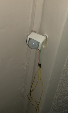
The red cell in the table indicates that there was some motion detected after the door has been locked. This is the proper introduction for the motion detection sensors: after adding door lock and temperature sensors, I wanted to add motion detection sensors inside the apartment. I have used HC SR-501 PIR motion detector:
I have three sensors placed around the apartment and I have a web page which updates the motion information in real time (WebSockets used):

Let us not forget the temperature and humidity sensors:


недеља, 20. август 2017.

Added telemetry to the toy car

This is a followup of my original post.

I have added a voltage readout of the battery in my toy car. It looks like this on client applications:
Java Swing application

Android application

Voltage is read using MCP 3008 A/D converter:
MCP 3008 A/D converter pinout

Here is the layout:

  • connect pins 16 (Vdd) and 15 (Vref) to the 3.3V pin of your GPIO port of your Orange Pi, or Raspberry Pi (they are pin-to-pin compatible),
  • connect pins 14 (Agnd) and 9 (Dgnd) to the GND pin of your GPIO port,
  • connect pin 13 (CLK) to the pin 23 of the GPIO port,
  • connect pin 12 (Dout) to the pin 21 of the GPIO port,
  • connect pin 11 (Din) to the pin 19 of the GPIO port,
  • connect pin 10 (CS) to the pin 24 of the GPIO port.
Make sure that SPI is enabled on your device. On my Orange Pi, it is was enabled by default. On Raspberry Pi, you need to start the raspi-config and enable SPI from the menu.
If the SPI is properly enabled, you will be able to see two files in the /dev folder of your Pi:
/dev/spidev0.0 and /dev/spidev1.0.

I have used Adafruit MCP library from this location.

When you download and install this library, you will use it by importing following modules:
import Adafruit_GPIO.SPI as SPI
import Adafruit_MCP3008 

Then you need to set it up:
# Hardware SPI configuration:
SPI_PORT   = 1
SPI_DEVICE = 0
mcp = Adafruit_MCP3008.MCP3008(spi=SPI.SpiDev(SPI_PORT, SPI_DEVICE)) 

On my Raspberry Pi, I have set the SPI_PORT variable to zero (0). On my Orange Pi, I had to set it to one (1). You can then read the voltage this way:
voltage = mcp.read_adc(0) 

The zero argument from the read_adc function is the number of the channel. In my case, I have connected the voltage from the battery to the pin 1 of the MCP3008, which is channel 0. Since the voltage of the fully charged battery can exceed 10V, I had to reduce the voltage:
Voltage reduction

I have extended my original Python server for the toy car to accept a telemetry request (string 't' as a telemetry request) and to send the voltage (currently it is just the voltage), as a JSON string:
elif text == 't':
voltage = mcp.read_adc(0)
c.send("{ \"voltage\": " + str(voltage) + '}\n')  

My client applications (both Java Swing and Android) send periodically this request string and receive a JSON string. Then they parse the JSON string, extract the voltage, and display it on the screen.

понедељак, 5. јун 2017.

Orange PI Zero and the Toy Car

This is a followup of my original post.

As I promised in my previous post, I am writing this post to share my experience with the Orange PI Zero and my toy car. The board is very small, and has almost all you need, except for the HDMI video output, which I don't need for my project. Therefore, it is perfect for me.

First of all, I have placed a small heat sink ond the SoC, since it can get quite hot (sometimes around 65°C). Next, I have placed the board on the car chassis and secured it with two screws. OPI Zero has both Ethernet and WiFi onboard, and even has the built-in antenna.

Since it does not have the HDMI, the only way I could configure it was to use the serial port. OPI has excellent support for serial console. Next to the Ethernet connector, there are three pins for Tx, Rx and GND. Thanks to that, I was able to set my WiFi using serial console, and from that moment on, I could SSH to it via WiFi.

OPI board 

The car now looks like this:

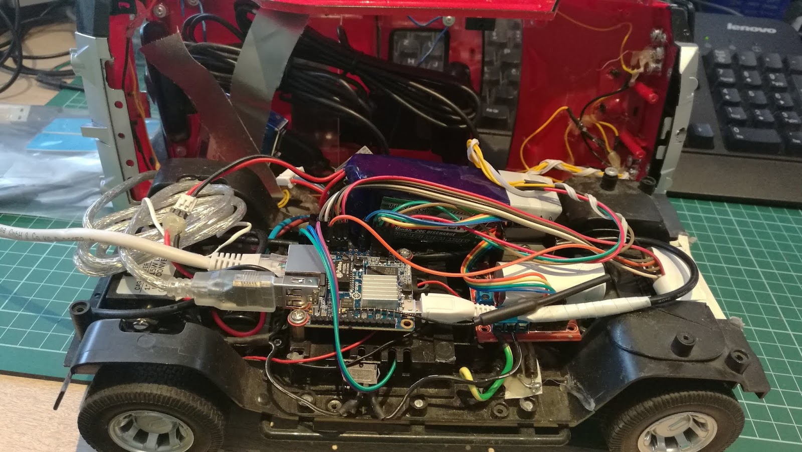
With everything added...

GPIO port does not have pins, so you need to solder them yourself. I have soldered seven pins (4 for the motor control, 2 for +5V/GND, and one for the signal which turns on/off headlights). You can see those seven pins on the top right corner of the picture above.

Next came the software. I want to state that the armbian support for the Orange PI is perfect. Everything works out of box. When I have configured the WiFi to connect to my home router, I was able to install all the software via SSH.

First I had to install the GPIO support. I have dowloaded and installed the orangepi_PC_gpio_pyH3 library, made by the duxingkei chow:

https://github.com/duxingkei33/orangepi_PC_gpio_pyH3

This library is similar to the one I have on the Raspberry Pi. Not the same - just similar enough.

The next step was to install the mjpeg streamer. I have installed it, but it could not run, saying that the libjpeg is missing. The only way I could make it work was to manually download the libjpeg8_8d1-2_armhf.deb file and to install it from that .deb file.

Next came the new kind of problem: mjpeg streamer crashed with this misleading stupid error message, when I tried to stream from two cameras at the same time:

Unable to start capture: No space left on device...

This does not have anything with the free drive space. It simply says that the complete bandwidth of the USB controller is consumed by the first web cam and it cannot stream from the second web cam. It simply cannot work with two Logitech C170 cameras.

I have tried to set the number of quirks for the driver, but it didn't work.

Fortunately, I had one Logitech C210 web cam (lower resolution - lower bandwidth) and that was good enough for the poor USB controller on the OPI Zero: one C170 (forward cam) and one C210 (rear cam).

The WiFi antenna is not so powerful as I have hoped, but it indeed works better than the small Realtek USB dongle which I had previously. The Ralink-based dongle and antenna I have described on my first post works the best, but I already have the built-in adapter and the antenna, so I will stick to that one.

That is about it. I am very satisfied with the Orange PI. I have tried both Lite and Zero boards, and they work excellent, considering the price and features. The only drawback of the Zero model is its limited USB bandwidth and the high core temperature. But, I can live with it...

понедељак, 8. мај 2017.

Toy Car v2.0

New version of the RPI-driven car

This is a followup of my previous posts: this and this.

I wasn't satisified with my previous build of the car. The bunch of wires was sticking all around the car. More important, the car just had a chassis with everything thrown on it. I wanted to have a complete car (with panels, headlights, etc.). That idea required to cut some wires, to solder instead of connect, to glue those wires with the plastic gun and so on. 

The result is here:


Here are some snapshots:
It looks nice, doesn't it?

I managed to put everything inside the car. Cameras, too.
 The front camera
 The rear camera

I started with the chassis. But this time, I have cut the wires to the appropriate length, used shrinking plastic insulator and screwed some components on the chassis:
The car inside looks neat now

I have used existing switch (from the original car setup - bottom left corner) to turn on/off the car. The switch is connected to the battery connector, so it controls the whole car. Now, when I want to use the car, I have just one connector to connect to the battery (top right corner of the photo).

The final assembly looks like this:
Added USB cams, headlights, A/D converter and serial port

I have ordered Orange Pi Zero to put instead of Raspberry Pi. I will write my experience with it when it arrives.

уторак, 9. фебруар 2016.

Raspberry Pi drives a toy car

Playing with Raspberry Pi

Followups:
added headlights to the car

I have used the Raspberry Pi in this project to control the toy car. I have a long history of remotely controlling stuff. Almost thirty years ago, I have made a board with relays to remotely control the toy car using ZX Spectrum 48 computer. At that time, I have purchased Z80 PIO chip, made a PCB board and soldered transistors, resistors and relays so I could drive the wired-controled toy car.

Last couple of years I was thinking of doing the same, but with the wirelessly-controlled car. I didn't want to use existing electronics and remote control that came with the toy car. I wanted to control the car using my computer.

I was looking at the old remotely controlled car which my kids used to play with. All the electronics was either broke, or missing. I just had the chassis with two motors: front to steer the car left/right and the back one to move the car forward/back. I figured out that I could use that car to play with. All I had to do was to get some controller and to wire that controller to some small computer that could be placed on the car. I was thinking of putting the smart phone on the car, but then the Rapspberry Pi came. Pi is much better choice, since it already has GPIO ports, while smart phones need some extra hardware (for example, the Android has IOIO hardware for that purpose).

So, this was my initial plan: get the Pi, get the controller, mount both on the car and make some software which would allow me to drive the car using my PC, or smart phone, by sending commands via WiFi. If I could mount some USB web cams on the car, even better.

This is the initial result:


The first car

I have purchased the controller based on the L298HN chip and placed that on the chassis:
It is quite easy to control the car using this piece of electronics. There are four pins at the lower right corner and they are used to control two motors: first two pins control the left/right motor, while next two pins control the forward/back motor.


The second car

I have purchased a Raspberry Pi to control the car. When it arrived, I have placed it on the car, but the car could not drive on carpets because the wheels were too small. So I bought a new toy car with bigger wheels and stripped all the electronics:

This was the initial configuration:
There is a LiFePo4 battery, voltage converter to 5V, with two female USB connectors, a Pi, and a driver. The battery has three cells, and gives 9.9V. I have put three diodes in series to lower the voltage for the motors (quick&dirty solution).

I have plugged the USB WiFi dongle into the Pi, so could I connect it to my home network. That way, I could send commands from my PC or smartphone and therefore control both motors (drive the car).

The first thing I did was to copy the Python test program to the Pi to see if I could control motors using the Python code:

#!/usr/bin/env python

import RPi.GPIO as GPIO
import time 

PORT_BACK = 26
PORT_FORWARD = 19
PORT_LEFT = 13
PORT_RIGHT = 6

GPIO.setmode(GPIO.BCM)
GPIO.setup(PORT_FORWARD, GPIO.OUT)
GPIO.setup(PORT_BACK, GPIO.OUT)
GPIO.setup(PORT_LEFT, GPIO.OUT)
GPIO.setup(PORT_RIGHT, GPIO.OUT) 

GPIO.output(PORT_FORWARD, 1)
time.sleep(1)
GPIO.output(PORT_FORWARD, 0)

GPIO.output(PORT_BACK, 1)
time.sleep(1)
GPIO.output(PORT_BACK, 0)

GPIO.output(PORT_LEFT, 1)
time.sleep(1)
GPIO.output(PORT_LEFT, 0)

GPIO.output(PORT_RIGHT, 1)
time.sleep(1)
GPIO.output(PORT_RIGHT, 0)
GPIO.cleanup() 

As you can see, it is quite easy to control motors using Python code on Pi. All you have to do is to send 1 to the port to turn on the motor, and 0 to turn it off.

The next thing was to make a Python application that would be a TCP/IP server. It would wait clients to connect and then would wait for commands, in form of strings. Clients would be either PCs, or smartphones. I have created a simple protocol to control the car. It is text-based and clients just send short strings which Python server receives, parses and executes. Here is the list:
  • F - turn on the forward/reverse motor to go Forward,
  • B - turn on the forward/reverse motor to go Back,
  • x - turn off the forward/reverse motor,
  • L - turn on the left/right motor to go Left,
  • R - turn on the lett/right motor to go Right,
  • X - turn off the left/right motor,
  • exit - client disconnects,
  • shutdown - shutdown the Pi,
  • reboot - reboot the Pi.
The client application can send combinations like: 'FL', or 'BL', meaning 'move forward and left', or 'move backwards and left'.

Then I have added two web cams: one for the front view, and the other one for the rear view:

I have installed the mjpegstreamer application which streams live webcam videos from both cams on the web server (two ports:8080 and 8081).

Then I have upgraded my client applications (both Android and Java Swing) to work with live streaming coming form the Pi. Both applications can connect to the Python server and mjpegstreamer at the same time. They show the live video stream from both cams, and send commands from the keyboard, or gamepad to the Python server:

Android app

Java Swing app

Schematics

Here is a simplified schematics:
Very simplified schematics

WiFi dongle problem

The USB WiFi dongle which people usually buy for the Pi has very small antenna (Realtek RTL8188CUS chipset). That antena is so small, that my car used to lose the WiFi connection in rooms not close to the home WiFi access point. That is why I have purchased another WiFi dongle, but with the bigger antena on it. However, this one had the Ralink chipsed, instead of Realtek. That was the problem since there was no support for the Ralink-based WiFi dongles in the Linux kernel prior to v4.0 (all this happened last year). So I had to make&install Linux kernel driver for it... Not the fun stuff. When the support for the Ralink dongles finally arrived (with the 4.0 kernel), I was able to use the dongle without building kernel drivers. Currently I have a Linux kernel v4.0 on my Pi, and the dongle works out of the box.

USB and Power problem

On my Pi I had three USB ports filled with devices (one WiFi dongle and two webcams). Pi cannot provide enough power on its four USB ports for all the devices I plugged in, so I had to put the powered USB hub. I had a spare female USB connector from the 5V voltage converter (the first one was used to power up the Pi). I have connected the power input of the USB hub to that other female USB connector:


The powered hub is below the webcam (the blue box). All USB devices are now plugged in it.

The current configuration looks like this: