недеља, 26. новембар 2017.

Custom made 16-bit CPU

I have created a custom made 16-bit CPU. I have used the LogiSim tool to create it. The CPU has three registers (A, B, and C), PC, SP, and some internal registers, such as MBR (Memory Buffer Register), IR (Instruction Register), and HIGH-BYTE register (keeps the upper 16-bit word of the  32-bit multiplication result, or a remainder when doing division).
Besides CPU, the system has 2x64KB of RAM and 16 words of text-based video memory, starting from the 0xfff0 address, and going to the 0xffff. The ALU is capable of doing all important operations including hardware-implemented multiplication and division. Both multiplication and division consume 32 cycles for 16-bit operands.


All the microcode is placed in two 32-bit ROMs:

There are around 100 instructions implemented: load/store, arithmetic, logical, shifting, jumps, calls, etc.
The CPU project is placed at the github: https://github.com/milanvidakovic/16-bit-CPU
The assembler for this CPU was forked from the original custom assembler and is also on the github: https://github.com/milanvidakovic/customasm
The output of the assembler are files in a such format that the LogiSim can load them into the RAM memory component.
The emulator was written in Java and it is capable of executing the machine code instructions which are the output of the assembler. It is also on the github:
https://github.com/milanvidakovic/16-bit-CPU-emulator

I have also created a transsembler which converts x86 assembler code made by the MS C compiler into the assembler for my custom CPU. That way, I can make a program in C and make it run on my CPU. The transsembler was written in Java and is also on the github: https://github.com/milanvidakovic/16-bit-CPU-transsembler

More sensors

This is a followup of my previous post.
I have managed to integrate multiple sensors into a single system capable of sensing if the entrance door is locked/unlocked, if there is a motion inside the apartment and to record the temperature and humidity.
It all started with the status of the entrance door. I wanted a system capable of sensing the status of the lock, but to be able to work without any electrical contacts, since it may corrupt the sensor in time. So I have found an inductive (contactless) switch and I have placed it in the entrance door of my apartment. It is connected to one of my raspberry pi computers, and it sends the information about the state of the door lock to my main server.
The Pi is glued to the wall next to the door:
You may wonder why are the headphones attached to the Pi. They emit the annoying sound of sine waveform, frequency of 3000Hz when the door is unlocked for more than one minute. That way I have a reminder that I need to lock the door.
The red LED is an indicator of the door lock status. If it is red, the door is locked. However, going to the door to see if it is locked or unlocked is not too attractive. I had to invent some way to know the door status without actually going to the door. That is why I have developed the Android application for it:
The lock icon goes red when the door is locked (the time is written below the icon), and goes green when the door is unlocked. The notification comes in real time thanks to the Google Cloud Messaging.
Next came the web portal. I wanted to have the history of door locking and unlocking. That is how I made this web page:

The red cell in the table indicates that there was some motion detected after the door has been locked. This is the proper introduction for the motion detection sensors: after adding door lock and temperature sensors, I wanted to add motion detection sensors inside the apartment. I have used HC SR-501 PIR motion detector:
I have three sensors placed around the apartment and I have a web page which updates the motion information in real time (WebSockets used):

Let us not forget the temperature and humidity sensors:


недеља, 20. август 2017.

Added telemetry to the toy car

This is a followup of my original post.

I have added a voltage readout of the battery in my toy car. It looks like this on client applications:
Java Swing application

Android application

Voltage is read using MCP 3008 A/D converter:
MCP 3008 A/D converter pinout

Here is the layout:

  • connect pins 16 (Vdd) and 15 (Vref) to the 3.3V pin of your GPIO port of your Orange Pi, or Raspberry Pi (they are pin-to-pin compatible),
  • connect pins 14 (Agnd) and 9 (Dgnd) to the GND pin of your GPIO port,
  • connect pin 13 (CLK) to the pin 23 of the GPIO port,
  • connect pin 12 (Dout) to the pin 21 of the GPIO port,
  • connect pin 11 (Din) to the pin 19 of the GPIO port,
  • connect pin 10 (CS) to the pin 24 of the GPIO port.
Make sure that SPI is enabled on your device. On my Orange Pi, it is was enabled by default. On Raspberry Pi, you need to start the raspi-config and enable SPI from the menu.
If the SPI is properly enabled, you will be able to see two files in the /dev folder of your Pi:
/dev/spidev0.0 and /dev/spidev1.0.

I have used Adafruit MCP library from this location.

When you download and install this library, you will use it by importing following modules:
import Adafruit_GPIO.SPI as SPI
import Adafruit_MCP3008 

Then you need to set it up:
# Hardware SPI configuration:
SPI_PORT   = 1
SPI_DEVICE = 0
mcp = Adafruit_MCP3008.MCP3008(spi=SPI.SpiDev(SPI_PORT, SPI_DEVICE)) 

On my Raspberry Pi, I have set the SPI_PORT variable to zero (0). On my Orange Pi, I had to set it to one (1). You can then read the voltage this way:
voltage = mcp.read_adc(0) 

The zero argument from the read_adc function is the number of the channel. In my case, I have connected the voltage from the battery to the pin 1 of the MCP3008, which is channel 0. Since the voltage of the fully charged battery can exceed 10V, I had to reduce the voltage:
Voltage reduction

I have extended my original Python server for the toy car to accept a telemetry request (string 't' as a telemetry request) and to send the voltage (currently it is just the voltage), as a JSON string:
elif text == 't':
voltage = mcp.read_adc(0)
c.send("{ \"voltage\": " + str(voltage) + '}\n')  

My client applications (both Java Swing and Android) send periodically this request string and receive a JSON string. Then they parse the JSON string, extract the voltage, and display it on the screen.

недеља, 2. јул 2017.

Home weather net

There is a followup of this post.
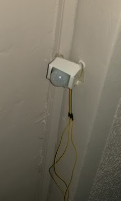
When I purchased Raspberry Pi starter kit couple of years ago, I got the DS18B20 sensor with it. It is a simple device, three pins only, uses one-wire protocol to send the measured temperature to the host computer. There are plenty of tutorials how to use it with the Raspberry Pi. 

I have connected that one sensor to the PI and was able to read the temperature.

Then I have purchased more DS18B20 sensors and placed one outside, in the shadow.


Then I have purchased DHT11 combined sensor for both temperature and humidity.

DHT11 sensor has a nice support for Python in this library.

Now I have four sensors, two for the inside temperature, one for the outside temperature, and one for the inside humidity. The next step was to make some web site for temperature reading. I have created a small web server which gathers data from all four sensors and displays it in two ways: gauges and charts:
This is nice, but I wanted an instant readout of the temperature, without a need for grabbing the nearest mobile phone, tablet, or computer and navigating to the web server. Then I remembered that I have two old Samsung Android phones: Samsung Galaxy Ace and Samsung Galaxy S+. Both have old Andorid OS, v2.3.6. Both have so small amount of RAM, that they are useless now (especially the Galaxy Ace). So, I have uninstalled everything and installed my own custom application, so those phones now have a new purpose:


Whenever I look at them, they display the time, date, and the temperature inside and outside. The data is displayed each second, moved to the right by one pixel, and then at the end of the line, moved by one pixel below, so the pixels are not burned.

Android phone runs without battery

Now I had two questions: will the display live, since I have turned off the screen saver, and what about the battery - can I run the mobile phone without a battery?

Well, the first question can be answered only by the experiment, and both phones now work for approximately half a year, and they still work.

The second question is more interesting: if I remove the battery, the phone will not work. Android is designed to work with the battery, and it needs software patches at very low level to turn off the protection which requires the battery to be present.

Now, there are plenty of tutorials how to make your Android phone work without a battery. Those tutorials work for older devices like these I have. It all comes to one thing: pretend that you do have a battery. How to do that? Here is what I have done.

First of all, the procedure differes for various phones. Even my two phones have different procedure. For the Galaxy Ace, it was the simple one. There are three pins inside the phone to which battery contacts connect when you insert the battery.

You can connect 5V (from the charger) to the plus pin, ground to the minus pin, and, for the Galaxy Ace, I simply shorted the 'B' pin to the minus pin. The battery voltage is 3.7V, but the phone works with 5V, too.


The picture above is the Galaxy Ace. No voltage regulators, and no resistors.

With the Galaxy S+, it was a different story. First of all, 5V and ground from the charger can be connected to the plus and minus pins, but the phone does not work reliably. I needed to step down the voltage. I have purchased a buck step down regulator, and lowered the voltage to 3.9V. Then I have tried various resistors between minus pin and 'B' pin, to find out that 10K Ohm resistor works nice. So, my final configuration includes voltage regulator to step down the voltage, and 10K resistor between 'B' and minus pins:


The picture above is the voltage regulator and the Galaxy S+. The resistor cannot be seen here, since it is placed inside the phone.

субота, 1. јул 2017.

Odroid XU4 boot from hard disk

I have Odroid XU4 computer. It is a nice piece of machine. It has 8 cores, Gigabit Ethernet, USB3.0. It can boot from uSD card, or eMMC module. However, I have experienced frequent uSD card crashes, so severe, that the Odroid wouldn't boot afterwards. It would happen when Odroid does some intensive write to the file system. It would simply mess up the file system beyond repair.

That is why I have decided to find instructions how to boot this device from a hard disk.

First of all, you cannot make your Odroid XU4 completely boot from the hard disk. It will start the boot process from the uSD card, and then it will mount the root file system on the hard disk, instead on the uSD card.

There is a nice post on the official Odroid forum. It says that you need to write the image on your uSD card and then boot the Odroid. When it boots successfully, you can then connect the external USB hard disk. Then you need to format that external hard disk to ext4 file system:

mkfs.ext4 /dev/sda1

Now you need to copy the content of the uSD root partition to the external hard disk:

mkdir /tmp/sda1
mount /dev/sda1 /tmp/sda1
rsync -avx / /tmp/sda1
umount /dev/sda1

After that, type blkid to see UUIDs of all disks connected to your Odroid. The output would be like this:

/dev/sda1: UUID="86135-2ba3-45cf-bda0-317b" TYPE="ext4" PARTUUID="ab57-01"
/dev/mmcblk0: PTUUID="3ceda53" PTTYPE="dos"
/dev/mmcblk0p1: SEC_TYPE="msdos" LABEL="boot" UUID="5A5A-6868" TYPE="vfat" PARTUUID="3cd53-01"
/dev/mmcblk0p2: LABEL="rootfs" UUID="e139-fe3-99859" TYPE="ext4" PARTUUID="3cd53-02"

Hard disk is /dev/sda1. You need to remember its UUID, since you need to put it in two places: /media/boot/boot.ini file, and /etc/fstab file (before unmounting the temporary mount, it was: /tmp/sda1/etc/fstab).

Make copies of both files, then edit the /media/boot/boot.ini file first. Find the line in which the root file system is mounted:

setenv bootrootfs “console=tty1
console=ttySAC2,115200n8 root=UUID=e139-fe3-99859 rootwait ro”

Substitute the original UUID with the UUID of the hard disk. This way, the Odroid will continue boot from the hard disk instead from the uSD card:

setenv bootrootfs “console=tty1
console=ttySAC2,115200n8 root=UUID=86135-2ba3-45cf-bda0-317b rootwait ro”

Next, open the /etc/fstab file (before unmounting the temporary mount, it was: /tmp/sda1/etc/fstab). Change the original UUID to the UUID of the hard disk:

UUID=86135-2ba3-45cf-bda0-317b / ext4 errors=remount-ro,noatime 0 1
LABEL=boot /media/boot vfat defaults 0 1

With this change, you will have the external hard disk permanently mounted.

I have written couple of instructions about setting up Raspberry Pi here.

недеља, 18. јун 2017.

A red button that really does something

I have a DLINK DNS-325 network storage and it can work as a print server. I have connected my HP LaserJet 1020 printer to it and for past six years I was able to print using that print server. However, whenever I needed to print on two sides, or needed to add more paper, or had a paper jam and then wanted to continue printing, I wasn't able to proceed with the print. The red LED would blink, but the printer doesn't have the button to continue printing.
When that printer is connected to your PC, the driver takes care of those situations and offers you to click somewhere on the screen to continue printing. With this print server, that option was no longer available.
That was quite unpleasant situation, but I was able to resolve it by finding out that on the internal NAS web site, among printer server options, there was a "Clear print queue(s)" button, which continues with the printing. I was able to figure out the URL which was hit by the button, and fortunately, that URL didn't require user to log on. The URL is something like this:


http://<NAS_IP_ADDRESS>/cgi-bin/system_mgr.cgi?cmd=cgi_clear_print


I have placed an icon on my desktop as a shortcut with the address above. However, that fix required me to leave the printer and go back to the computer to click on that icon on my desktop, to continue with the printing. That is where one of my raspberry pi devices came in - I have connected a button to the pi and whenever I press that button, the Python code visits the URL above and flushes the print buffer, continuing the print.


Here is the Python code:

def edge_detected(channel):
print 'EDGE detected, channel is ', channel
val = GPIO.input(PORT_SWITCH)
if val == 0:
print "FLUSH!"
try:
r = requests.get('http://x.y.z.w/cgi-bin/system_mgr.cgi?cmd=cgi_clear_print') 
print r.text
except:
print str(sys.exc_info())

GPIO.add_event_detect(PORT_SWITCH, GPIO.BOTH, callback=edge_detected, bouncetime=50) 

The code above uses the Requests library.

One day I will connect my printer to the RPI instead of NAS, but so far, this works.

понедељак, 5. јун 2017.

Orange PI Zero and the Toy Car

This is a followup of my original post.

As I promised in my previous post, I am writing this post to share my experience with the Orange PI Zero and my toy car. The board is very small, and has almost all you need, except for the HDMI video output, which I don't need for my project. Therefore, it is perfect for me.

First of all, I have placed a small heat sink ond the SoC, since it can get quite hot (sometimes around 65°C). Next, I have placed the board on the car chassis and secured it with two screws. OPI Zero has both Ethernet and WiFi onboard, and even has the built-in antenna.

Since it does not have the HDMI, the only way I could configure it was to use the serial port. OPI has excellent support for serial console. Next to the Ethernet connector, there are three pins for Tx, Rx and GND. Thanks to that, I was able to set my WiFi using serial console, and from that moment on, I could SSH to it via WiFi.

OPI board 

The car now looks like this:

With everything added...

GPIO port does not have pins, so you need to solder them yourself. I have soldered seven pins (4 for the motor control, 2 for +5V/GND, and one for the signal which turns on/off headlights). You can see those seven pins on the top right corner of the picture above.

Next came the software. I want to state that the armbian support for the Orange PI is perfect. Everything works out of box. When I have configured the WiFi to connect to my home router, I was able to install all the software via SSH.

First I had to install the GPIO support. I have dowloaded and installed the orangepi_PC_gpio_pyH3 library, made by the duxingkei chow:

https://github.com/duxingkei33/orangepi_PC_gpio_pyH3

This library is similar to the one I have on the Raspberry Pi. Not the same - just similar enough.

The next step was to install the mjpeg streamer. I have installed it, but it could not run, saying that the libjpeg is missing. The only way I could make it work was to manually download the libjpeg8_8d1-2_armhf.deb file and to install it from that .deb file.

Next came the new kind of problem: mjpeg streamer crashed with this misleading stupid error message, when I tried to stream from two cameras at the same time:

Unable to start capture: No space left on device...

This does not have anything with the free drive space. It simply says that the complete bandwidth of the USB controller is consumed by the first web cam and it cannot stream from the second web cam. It simply cannot work with two Logitech C170 cameras.

I have tried to set the number of quirks for the driver, but it didn't work.

Fortunately, I had one Logitech C210 web cam (lower resolution - lower bandwidth) and that was good enough for the poor USB controller on the OPI Zero: one C170 (forward cam) and one C210 (rear cam).

The WiFi antenna is not so powerful as I have hoped, but it indeed works better than the small Realtek USB dongle which I had previously. The Ralink-based dongle and antenna I have described on my first post works the best, but I already have the built-in adapter and the antenna, so I will stick to that one.

That is about it. I am very satisfied with the Orange PI. I have tried both Lite and Zero boards, and they work excellent, considering the price and features. The only drawback of the Zero model is its limited USB bandwidth and the high core temperature. But, I can live with it...

понедељак, 8. мај 2017.

Toy Car v2.0

New version of the RPI-driven car

This is a followup of my previous posts: this and this.

I wasn't satisified with my previous build of the car. The bunch of wires was sticking all around the car. More important, the car just had a chassis with everything thrown on it. I wanted to have a complete car (with panels, headlights, etc.). That idea required to cut some wires, to solder instead of connect, to glue those wires with the plastic gun and so on. 

The result is here:


Here are some snapshots:
It looks nice, doesn't it?

I managed to put everything inside the car. Cameras, too.
 The front camera
 The rear camera

I started with the chassis. But this time, I have cut the wires to the appropriate length, used shrinking plastic insulator and screwed some components on the chassis:
The car inside looks neat now

I have used existing switch (from the original car setup - bottom left corner) to turn on/off the car. The switch is connected to the battery connector, so it controls the whole car. Now, when I want to use the car, I have just one connector to connect to the battery (top right corner of the photo).

The final assembly looks like this:
Added USB cams, headlights, A/D converter and serial port

I have ordered Orange Pi Zero to put instead of Raspberry Pi. I will write my experience with it when it arrives.